EVO II
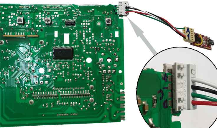
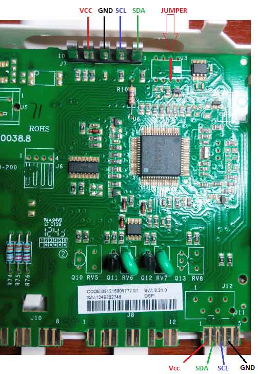
The pinout of the service connector and the pinout of the connector to the display board is shown below. Currently, work with EVO II PCB is supported only with the Elinv Prog tool (FT232RL), see the links below:
It is preferable to supply 5 volts to the electronic power module.
However, if the module does not work, try applying 3.3 Volt power.
If you use the power from the programmer device and it is 3.3 Volts, then to record the firmware you need to make a jumper between the 2nd and 7th pins of the memory chip (24C64). For example, as shown in the figure (JUMPER).
If a 5 volt power supply is used, a jumper is not required.
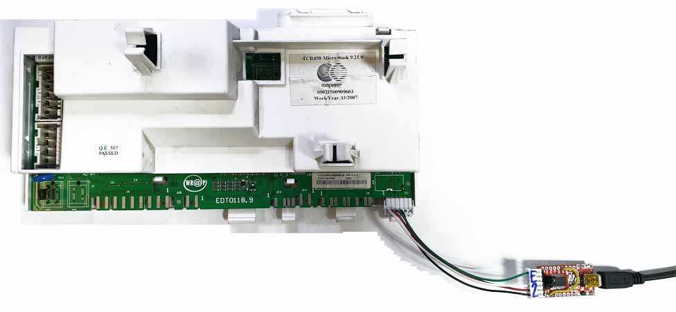
The following figure shows an example of connecting the programmer on the FT232RL chip and the E2 connector according to the SPP scheme.
The three-phase module is connected in the same way.
The connector pinout of this module of the Low End series differs from EVO 2. To connect the programmer to the module, a connector according to the A1 or A3 scheme is suitable.
If 3.3 Volts is set in the programmer, then to program the PCB, it is necessary to make a jumper between the 2nd and 7th legs of the memory chips (U2).
If a 5 Volt supply is used, no jumper is required.