USB FT232RL chip
Analog of USB Elinv Prog programmer device (connection via USB port), performed on FT232RL chip.
|
|
This page provides information about the programmer for the EP function, as well as Candy and Atlant. For information about the programmer for the RS function, see the corresponding section RS Serial Programmer |

|
|
To use this device you will need to install the driver. The distribution for Windows x86 and x64 can be downloaded here: http://skyprog.net/ru/CDM%20v2.12.00%20WHQL%20Certified.zip |
This device successfully replaces the USB Elinv Prog, although the design is simpler and much less expensive.
If the drivers are installed correctly (see USB Elinv Prog section), the device will be determined by the Sky Prog Programmer software as the USB Elinv Prog device.
You can buy, for example, on aliexpress.com. The price is very low, 3-4 $.
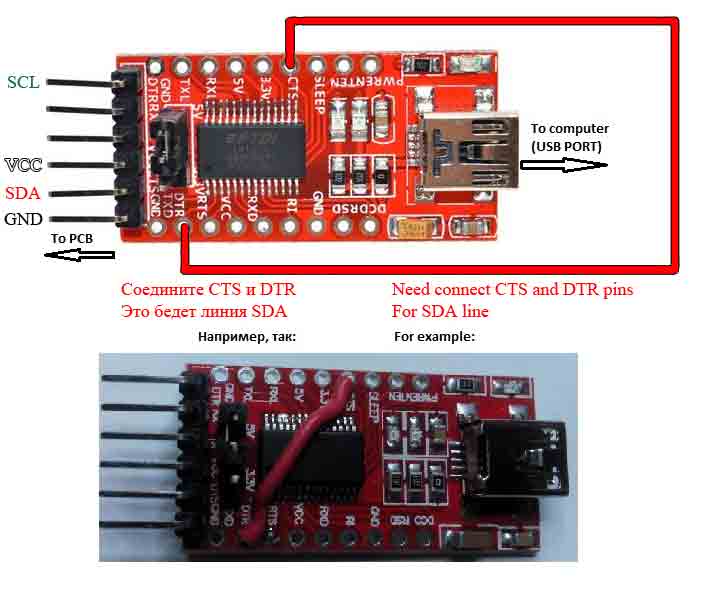
The figure below shows which device points are needed for the connection to the PCB.
Power can be used 5 volts or 3.3 volts.
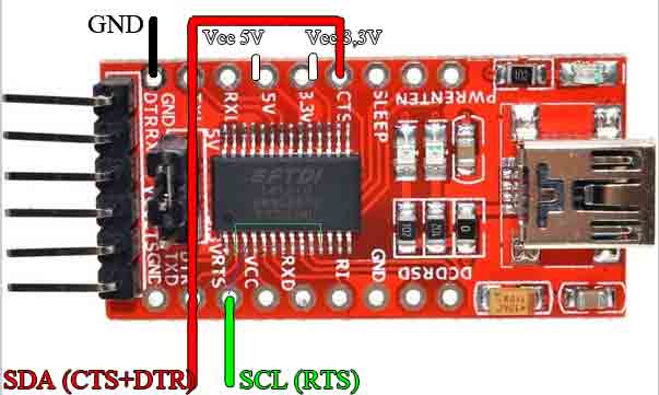
For work you need connect together the CTS and DTR pins. It is the SDA line.
Also do not forget for an Indesit arcadia PCB the power supply must be 5 Volt, and for Candy only 3.3 Volt.
There are other options on the FT232RL chip, there are a lot of them on the Chinese website aliexpress. Almost all of them are suitable for programming modules using the software Sky Prog Programmer. You need to find the right points for connection and make wires from them to the PCB.
Below is a specific example of adapting the simplest converter for Sky Prog Programmer according to the SPP scheme.
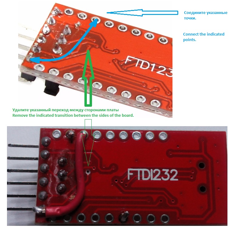
1. Modification on the upper side of the board:
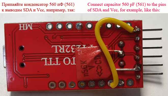
2. Modification on the back of the board:
|
|
Attention! In program version 1.14, a new mode of working with this programmer in bitbang mode has appeared, and starting from version 1.15 it is already set by default: FT_MODE = 1 (see program settings). When the programmer works in this mode, the following modification is not required! |
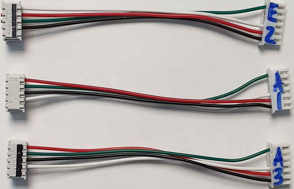
3. Make connectors E2, A1, A3 according to the SPP scheme, observing the color sequence:
4. Connect the programmer to the module, below is a picture with an example on ARCADIA 3:
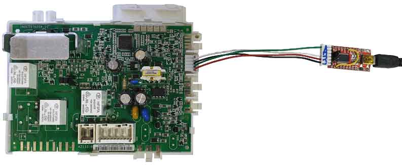
With this connection to the ARCADIA PCB, set the jumper to 5 volts.
The adapter and connector are ready for programming.
Connection to PCBs is in the section:
Ready-made programmers and connectors can be purchased on the program website.